NASA Technical Reports Server (NTRS) 20120003469: Thermal Insulation Test Apparatuses PDF
Preview NASA Technical Reports Server (NTRS) 20120003469: Thermal Insulation Test Apparatuses
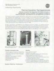
National Aeronautics and Space Administration John Kennedy Space Center, F. FL Technology Opportunity Thermai insulation Test Apparatuses Thermal Insulation Test Apparatus With Sleeve (Cryostat 1) Multipurpose Thermal Insulation Test Apparatus (Cryostat 2) Thermal Insulation Test Apparatus for Flat Specimens (Cryostat 4) The National Aeronautics and Space Administration (NASA) seeks to license its Thermal Insulation Test Appara- tuses. Designed by the Cryogenics Test Laboratory at the John F. Kennedy Space Center (KSC) in Florida, these pat- ented technologies (U.S. Patent Numbers: Cryostat 1 - 6,742,926, Cryostat 2 - 6,487,866, and Cryostat 4 - 6,824,306) allow manufacturers to fabricate and test cryogenic insulation at their production and/or laboratory facilities. These new inventions allow for the thermal performance characterization of cylindrical and flat specimens (e.g., bulk-fill, flat-panel, multilayer, or continuously rolled) over the full range of pressures, from high vacuum to no vacuum, and over the full range of temperatures from 77K to 300K. In today's world, efficient, low-maintenance, low-temperature refrigeration is taking a more significant role, from the food industry, transportation, energy, and medical applications to the Space Shuttle. Most countries (includ- ing the United States) have laws requiring commercially available insulation materials to be tested and rated by an accepted methodology. The new Cryostat methods go beyond the formal capabilities of the ASTM methods to provide testing for real systems, including full-temperature differences plus full-range vacuum conditions. —s Cryostat 1 - r' '1 " Cryostat _-- /'gtH - Figure 1 Overall view o Cryostat-1 with Figur 2. Vicw o Cryostat-2 showing the cold- Figure 3 Overall view of Cryostat-4. the vacuum can assembly removed, mass assembly mounted on a workstand. Potential Commercial Uses Benefits • Thermal conductivity measurement for perfor- • New standard test method mance qualification of statistical quality control • Relatively quick testing • Performance range determination of standard • Mobile and adaptable to different sizes and thicknesses product lines • Requires minimal user intervention • Assistance in new product development • High sensitivity and excellent repeatability • Multilayer insulation (MLI) • Produces long-duration, steady-state measurement of heat • Process piping and storage tanks flux through insulation test article • Research and testing • Provides flexibility of pressure environments • Refrigeration • One-step cooling, filling, and thermal stabilization process • Displays complete temperature profile across thickness of insulation test article for detailed performance information -- ExpTOfe. Discover. (JdTä1d - TheTechnolqgy _____ ___ Cryostat 1 is a cylindrical test apparatus for direct measurement of the absolute thermal conductivity of a material system. This apparatus, shown in Figure 1, includes a cold mass and provides absolute k-values for specimens. A simplified schematic of the insulation test apparatus is given in Figure 4. Cryostat 2 is a cylindrical test apparatus for measurement of the comparative k-value (see Figure 2). This apparatus includes a cold mass and accepts specimens up to 50 mm thick. An overall diagram of Cryostat 2 is given in Figure 5. Cryostat 4 is a flat-plate test apparatus used for comparative k-value measurements. An overall view of this appa- ratus is shown in Figure 3. The Cryostat 4 cold-mass assembly can be configured for rigid or soft materials, with or without compressive loads applied. An optional load cell assembly can also be provided. A simplified schematic of the test apparatus showing the temperature sensor locations is given in Figure 6. Options for Commercialization NASA seeks qualified companies to commercialize these Thermal Insulation Test Apparatuses. These and other technologies are made available by the KSC Technology Transfer Office through a variety of licensing and partner- ing agreements. Contact If your company is interested in the Thermal Insulation Test Apparatuses or if you desire additional information, please reference Case Numbers KSC-12107, 12108, or 12390 and contact: Maria Ray, Technology Transfer Office, Mail Code: YA-C1, Kennedy Space Center, FL 32899. Telephone: (321) 867-1463, FAX: (321) 867-2050, [email protected] Cold Mass Bootf Flow - Assembly Insulation Heater Measa,ennent •CM1 I Ch. b.e ro-n Upper Vacuum LN FJl a,,d Verd II CGhaumardb er Chapir FSeeendstohrrotugtt SFeeendsotirv uiugh 11 TIl VCI Upper Aeroget vacaur,, insulation Guard Stack _// Measurement Jl r Material tnsularon Test Materau . .vcs .6 Heater Chamber iT2 T12 VC2 vCi 1T45 TLaNn k I VCahcauummb e- I I- .dero.:: T3 t VC7 T3 T13 VC3 Surface Temperature Measurement VC3 I Vacua,,, Sensor Location Lower Pomp CGhaumardb er __________ GLOawraO 'S AteamcOc, el Ti1. 213 Cold-BounTdoapry C Toeldm-Mpearsast ure (CBT) T4. 15 Warm-Boundary Temperature (W81) VCt. VC2, VC3 Vacuum Chamber Eetencr CM2 lT.hicknaess.. I Wen'SCaC VC4. VC5, VC6 Heater Temperature Figure 6. Simplified schematic of Cryostat 4 Surface Temperature Measurement Surface Temperature Measurement showing typical locations of temperature Sensor Location Sensor Location sensors. VC1 VC2. VC3 Vacuum Can Temperature Ti 'mccc Layer Cold-Mass). CUT 111, 112, 113 Warm-Boundary Temperature (WBTI T2, 13, T4 Middle Layers Ti, 12. T3 Cold-Boundary Temperature (CBTI 15 Outside Layer, WBT CM1 .CM2 Cold-Mass Temperature VCI, VC2, VC3 Vacuum Chamber ExterIor Figure 4. Simplified schematic of cryostat i Figure 5. Simplified schematic of Cryostat 2 show- showing typical locations of temperature ing locations of temperature sensors and -sensors. equipment. The United States Government does not assume any liabihty resulting from use of this information and does not represent or warrant that use of the informaben will be free from privately owned tights. In addition, the United St ales Government does riot endorse any commercial product, process, or activity identified in this publication.
