Configuration Options: Connecting Concepts Why Airplanes PDF
Preview Configuration Options: Connecting Concepts Why Airplanes
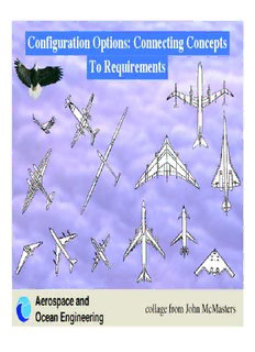
Configuration Options: Connecting Concepts Why Airplanes Look Like They Do To Requirements W. H. Mason Aerospace and Ocean Engineerin g collage from John McMasters slide 1 2/19/03 A new capability Technology someone might advances? pay to have? Designer How to exploit technology for capability? Configuration Concept Airplane Shapes Change to Exploit Advances in Technology Aerospace and Ocean Engineerin g slide 2 2/19/03 To Start: Define a Mission What is the airplane supposed to do? • How far does it go? How fast? • What and how much does it carry? • What are the landing and takeoff requirements? • Are there any maneuver/accel requirements? (these are known as point performance req’ts) • What MIL or FAR req’ts must be satisfied? Taken together, the answers to these questions are known as the Mission Statement, and also imply that you think of concepts to do the job Aerospace and Ocean Engineerin g slide 3 2/19/03 We Define Mission Segments Each Segment Can Influence the Concept BCA: best cruise altitude BCA, BCM: best cruise Mach specified M 6+ 7 5+ Altitude combat 5 6 4 3 BCA,BCM 8 R R 7 subsonic supersonic 2 1 Radius Aerospace and Ocean Engineerin g slide 4 2/19/03 Configuration Concept: • Lifting surface arrangement • Control surface(s) location • Propulsion system selection • Payload • Landing Gear Wright Brothers: • Light weight propulsion • Innovative control concept (more important than stability) • Continual design evolution/refinement Aerospace and Ocean Engineerin g slide 5 2/19/03 Good Aircraft • Aerodynamically efficient, including propulsion integration (streamlining!) • Must balance near stability level for minimum drag • Landing gear must be located relative to cg to allow rotation at TO • Adequate control authority must be available throughout flight envelope • Design to build easily (cheaply) and have low maintenance costs • in 1990s: quiet, nonpolluting Aerospace and Ocean Engineerin g slide 6 2/19/03 Conventional Subsonic - A Baseline • Payload distributed around cg • Longitudinal control power from tail (with moment arm) • Vertical Tail for directional stability, rudder for control • Wing/Fuselage/Landing Gear setup works • Minimum trimmed drag at near neutral stability Aerospace and Boeing 747-400, source: www.boeing.com Ocean Engineerin g slide 7 2/19/03 Configuration Options • Where do you put – the wings? – the engines (in fact, what kind?) • Where do you put the control surfaces? – what options are available? • Do you have room for the landing gear? • Possible innovative designs? Aerospace and Ocean Engineerin g slide 8 2/19/03 Why Sweep the Wing? Subsonic (usually small) • Adjust wing aero center relative to cg • On flying wing, get moment arm length for control Transonic (significant, 30°-35°) • Delay drag rise Mach (compressibility effect) - definition of the drag divergence Mach no.? Supersonic (large, 45°-70°) • Wing concept changes, - must distribute load longitudinally as well as laterally • reduce cross-sectional area and area variation Wing sweep increases wing weight for fixed span Aerospace and Ocean Engineerin g slide 9 2/19/03 The classic large airplane: The Boeing 747 source: www.boeing.com Aerospace and Ocean Engineerin g slide 10 2/19/03
Description: