Computer Aided engineering - IABG PDF
Preview Computer Aided engineering - IABG
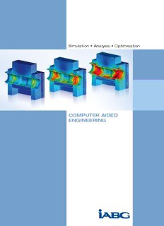
Simulation • Analysis • Optimisation Computer Aided engineering Computer Aided Engineering Simulation • Analysis • Optimisation Simulation • Analysis • optimisation Increasing demands on new products in terms of functionality, quality, costs and development time can only be met by employing the latest in CAE methods on powerful computers. Mastering a wide range of methods is essential for virtual product develop- ment. We can actively support you in this respect with over 30 years of experience and expertise. On request, we run relevant tests at our own test facilities in addition to our computing services. We also offer you independent develop- ment of components in cooperation with our various specialist departments. Our forte lies in analysing and providing solutions for innovative and complex tasks. The primary aim is always to improve the quality of your products, reduce costs and shorten development time. We use a variety of standard CAE tools for our simulations. Our service portfolio CAD design, FE modelling Strength analysis, joining techniques Fatigue Strength Structure optimisation Oscillation, vibration Non-linear structural dynamics, Shock, fluid-structure interaction Flow simulation, temperature fields Method development, software development Fields of application Automotive Aerospace Rail vehicles Defence technology Materials-handling technology Production technology Test planning Wind energy Verification of test rig for fatigue tests Strength evaluation for demolition excavator for dismantling nuclear power plants CAd design, Fe modelling We produce designs according to your specifications or modify analysed designs based on calculation results. We employ parametric 3D CAD sys- tems to enable quick and flexible adaptation of geometries. Conclusive calculation results require appropriate FE models that are matched to your particular specifications and conditions. In the modelling process, standard-format 2D and 3D CAD geometries are imported. The data is corrected and prepared for meshing. Depending on the application we use beam-, shell- or solid elements with automatic tetrahedron or hexahedron meshing. Software used Catia V5, Pro/E Medina, ANSA HyperMesh, MSC.Patran, RStab Strength analysis, joining techniques We examine the structural properties of your designs and connections using linear and non-linear FEM as well as analytical methods to give impulses for focused improvements. We perform computerised strength analyses in compliance with all the current standards and guidelines. In cooperation with our test departments, we provide independent planning and administration of tests, for example for validating and determining load data and material parameters. Software used Above: Model of a crankshaft segment MSC.Nastran, MSC.Marc, ANSYS, Abaqus, MDesign, Hexagon Centre: Strength analysis of a differential cage Below: Buckling analyses for CFRP structures 4 5 Elastic-plastic fracture simulation of a pedal box Fatigue Strength We employ computer analyses to help you optimise your components and testing procedures and implement the resulting concepts in design. Our specialists in multibody simulation, test bench development and fatigue testing provide tailored solutions for your specific tasks: Load data simulation using MBS or global FEM models Numerical fatigue life assessment Damage based shape optimisation Fatigue life assessment in compliance with industry-specific standards and regulations Accompanying fatigue testing Software used FEMFAT, nCode DesignLife, Rifest Above: Fatigue life assessment of a swivel bearing Structure optimisation Permanent increasing demands for lightweight components require the Centre: Parameter use of CAE methods in the early development phase to optimise com- optimisation of a vehicle framework structure ponent geometry. In the process, we perform optimisation analyses with static and dynamic load cases, taking into account restrictions such as stiffness requirements. Manufacturing constraints can also be considered Below: Topology at this stage, so that the boundary conditions that apply to the subsequent optimisation of a rear axle gear housing manufacturing process become part of the optimisation. We provide the following range of services for optimising your component structure: Topology optimisation to determine the optimum component shape based on the available space Refeeding of the optimum shape in a CAD model Shape optimisation to further improve stress distribution at critical zones Numerical optimisation of designed space and wall thickness with parameterised concept models Predictions about the functional feasibility of a new development and dimensioning of an optimum structure Software used TOSCA, Optistruct, MSC.Nastran 6 7 Shock analysis of Frigate F124 oscillation, vibration Our service portfolio ranges from modal analysis to response analysis through to transient dynamic calculation and earthquake simulation. A validated FE model is required for quantitative prediction of vibration properties. We create these models based on measured dynamic proper- ties or we rework existing models. The objective is to achieve the best possible match between the Eigen frequencies and natural modes based on experiments and simulation. This model update can be achieved manually or by using numerical optimisation methods. Software used MSC.Nastran, ANSYS, Abaqus non-linear structural dynamics, shock, fluid-structure interaction Our experience in the numerical analysis of highly dynamic loaded compo- nents and complete systems for all sorts of terrestrial, naval and airborne vehicles as well as for stationary objects provides you with benefits regard- ing the following phenomena: Large-scale deformation, fracture and post-fracture behaviour Plasticity and strengthening as a function of the strain rate Inhomogenity and anisotropy of stiffness (fibre composite material) Rubber-elastic behaviour (elastomers) Fluid-structure interaction in the case of detonations Propagation of stress waves Above: Arrival of shock wave on structure Our service portfolio Safety analyses with regard to deformation, failure and shock Centre: PSD response Crashworthiness for vehicles and transport containers analysis of fuel tank (e. g. CASTOR casks) Simulation of the opening behaviour of convertible tops Simulation of penetration processes, e. g. turbine blade impacting turbine Below: Crash simulation housing of a shield dome during dismantling of a nuclear Pyroshock loading of aerospace structures power plant Pre- and post-shot analyses of underwater explosions including technical consulting for experiments Analysis of survivability/vulnerability of ships, submarines and other underwater vehicles Software used DYSMAS, DYNA, Abaqus, ANSYS, PAMCRASH 8 9 Examination of turbulent kinetic energy while helicopter landing
Description: